equa-logo

Exhaust air heat pump


Challenge


In today's IDA ICE we have the possibility to create more advanced plant models by using ESBO Plant. By using ESBO plant it is possible to automatically create plants that for example use the exhaust air as a source for a heat pump. This can be useful when you need a rough estimation of the savings that can be achieved. However, a plant made in this way doesn´t coverer all aspects of a real plant design and will not simulate the true behavior of a real system layout. Luckily this is not a big problem, when using IDA ICE it is possible to create a plant model that looks like and simulates the real behavior by using the component models of the ESBO plant. In this particular case an exhaust air heat pump that works together with a district heating system was to be created. 
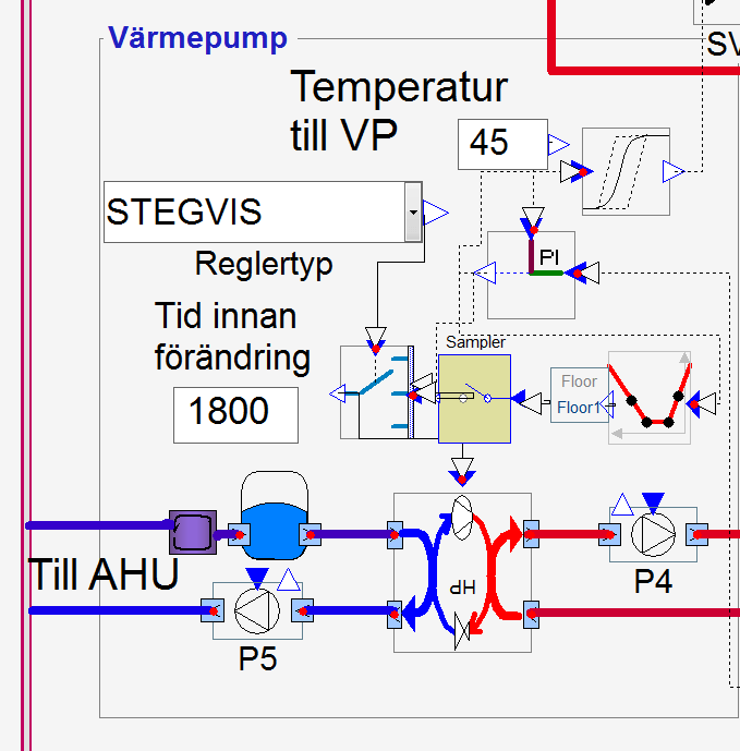
 

Solution

The model of an exhaust air heat pump consist of two main parts, the plant and the air handling unit with the exhaust air cooling coil. A normal plat in IDA ICE is unlimited, but when using detailed plant all valves, heat exchanges, the heat pump etc. must be properly sized. The sizing data to be put into the model can be reached by clicking the buttons in the top right corner of the model.

The air handling unit consists of an exhaust fan and a cooling coil. The coil is connected to the plant by using the built in connection between the plant and cooling coil. A project can consist of multiple air handling units connected.

The heat pump is controlled to keep the return water temperature at a constant level. To simulate a heat pump with multiple compressors that gradually steps into action it is possible to set the type of control to stepwise. The minimum time for each step can be varied. This will make the simulation quite slow. The model will work better if it´s possible to use continuous control.


Result

By using a more detailed simulation model the customer can test the influence of the sizing of the components on the energy usage.  Most important is the sizing of the heat pump and the tank connected to it. Also, by using this plant the model gives a correct result of the used power for heating that is requested to be within a certain limit according to the Swedish building code 
   
Sector
  • Residential
Categories
  • Detailed studies
Features
  • Customized designed HVAC systems


01a

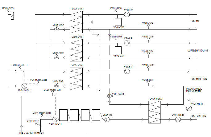
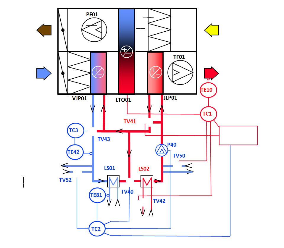
Figure 1: The schematic of the system to be designed.


01b

Figure 2: The resulting plant model in IDA ICE


01c

Figure 3: The Air handling unit connected to the Plant model.


01dFigure 4: A detailed view of the control of the heat pump. Here two different control algorithms can be selected stepwise or continuous.


Imprimer E-mail

University of Jyväskylä


Challenge

The aim of the study was evaluate low temperature heating and high temp cooling system solution development Sensus, which is developed by Are (one of the biggest HVAC contractors in Finland), in the modern university office building. One of the key elements in the Sensus system is to make cooling power into chilled panels with preheating coil of the ventilation system. And also the automation system is advanced compared to typical solutions. The challenge was to make a fair and reliable comparison between traditional system and Sensus.

(For more information about Sensus system)

The combined heating and cooling radiant panel system with quite large surface area allowed intermediate heating and cooling. Optimal free cooling usage. Heat load usage of datacentre in building service systems. Demand control of artificial light CO2-based demand ventilation Compared to traditional system Sensus system gave 15 % computational energy savings in heating (wo DHW) 28 % computational energy savings in cooling electrical energy


Solution

The combined heating and cooling radiant panel system with quite large surface area allowed intermediate heating and cooling. Optimal free cooling usage. Heat load usage of datacentre in building service systems. Demand control of artificial light CO2-based demand ventilation.


Result

Compared to traditional system Sensus system gave:

  • 15 % computational energy savings in heating (wo DHW)
  • 28 % computational energy savings in cooling electrical energy


Sector
  • Office
Categories
  • Whole-building studies
Features
  • Control systems
  • Cooling and heating
  • Customized designed HVAC systems
  • System and plant sizing
  • Ventilation


02a

Figure 1. Whole building


02bFigure 2. Sensus air handling unit


02c

Figure 3. Detailed occupancy profile.


Imprimer E-mail

Zero energy school house 


Challenge

In Luxemburg, a school house is planned to meet extreamly high requirements concerning lifetime energy balance. Dynamic simulation was used to investigate and evaluate the supply of fresh air, heat and light into the proposed building, relating to expected climatic conditions and utilizations. 


Solution

In order to get as realistic load profiles as possible for the plant, the occupancy profiles were adapted to meet the existing class schedules for individual class rooms on the one hand, and for the whole building on the other hand. To be able to quantify demand variation due to climatic conditions, one year with “average” weather was compared with another year with “extreme” weather (cold winter and low solar radiation). 


Result

With the "Passivhaus Projektierungspaket" (a monthly static method), the yearly used energy demand for room heating was determined to  50.000 kWh. The results of the simulation were 42.000 kWh of delivered energy for the "normal" year and 71.000 kWh for the "extreme year". The heating season lasts 4 months from mid November to mid March. 
   
Sector
  • Educational
Categories
  • Whole-building studies
Features
  • Airflow
  • Control systems
  • Cooling and heating
  • Ventilation


03a


03b

03c

03d

03e 


Imprimer E-mail

SOCIAL MEDIA